Lately I’ve been experimenting with a magnetic stripe card reader. In summary, I bought the cheapest one I could find on Amazon, opened it up, soldered some wires to it, added some electronic components, plugged it to my computer’s microphone socket and recorded things like this: the raw signal read from a magnetic stripe. In this post I’ll explain how magnetic stripe cards work and how to decode them.
Magnetic stripe cards were invented by Forrest Parry in 1969, which was quite the prolific year for giant leaps for humankind. The first company to develop and produce those cards was IBM, which chose to leave the basic ideas “open” for the rest of the industry to develop their own card systems. Some time later, the banking and airline industries met up and defined a set of standards so that all magnetic stripe cards would have the same size, their magnetic stripes in the same position, use the same encodings, etc.
The magnetic stripe is the usually dark-colored strip that appears in the back of the card. The data in the card are recorded in the magnetic stripe, but before I can talk about how those data are stored, I need to talk about magnets.
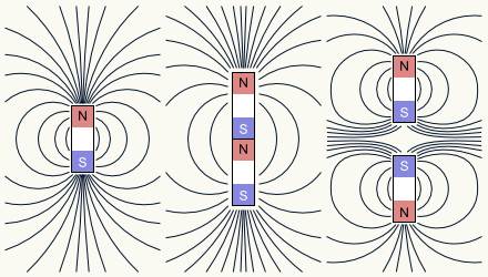
Imagine you have a magnet in the shape of a straight rod. One end of the rod is the magnet’s “North pole” and the other end is the “South pole”. The magnet produces a magnetic field, which is represented using “force lines” which go out of one pole into the other pole. Where the force lines are denser, the magnetic field is more intense. Almost all force lines go out or in through one of the poles, so that’s where the magnetic field has its highest intensity. This means that if you take a lump of iron and you move it close to a magnet, it will be attracted with more force towards a pole than towards, say, the center of the rod, where the force lines are more separated.
If you take two magnets and try to join them end to end, two things may happen. The first possibility is that you are trying to join a magnet’s North pole with the other magnet’s South pole. In this case, both magnets’ force lines will combine and, when the two magnets touch, they’ll behave as if they were a single magnet that’s twice as long: the two poles that touch disappear, and only the two free poles remain, where the combined magnet’s force lines go out and in. If, on the other hand, you were trying to join the same pole in both magnets, the two magnets will start to repel each other, the force lines will squish together between the magnets because they will not cross, and the intensity of the magnetic field between the magnets will increase. As the magnets come closer, the repulsion force increases and with it the intensity of the magnetic field.
A magnetic stripe is made up of many magnetic particles which behave like tiny magnets. Imagine that all those particles are oriented with the North pole to their right. In this case, the magnetic stripe would behave like a single magnet with its North pole to the right and its South pole to the left, with its most intense magnetic field on each end of the stripe. However, it’s possible to use a permanent magnet or an electromagnet to reverse the orientation of some particles. In this case, there will be an intense magnetic field in the regions that separate the particles with different orientations. A “write head”, which is an electromagnet, can set the orientation of the particles located underneath.
If the write head is moved from one side to the other as it induces one or other orientation, the magnetic stripe ends up looking like a series of magnets that are joined pole-to-same-pole. The magnetic field in this magnetic stripe will have intensity peaks where the same poles of two magnetic domains meet. Those intensity peaks can be detected using a “read head”, which is a device that produces a small electric current when it’s exposed to a magnetic field with changing intensity. By swiping this read head on the magnetic stripe, the differing intensity in different spots of the magnetic stripe causes electric current pulses to be produced: in one direction if it’s two North poles that meet, or in the opposite direction if it’s two South poles.
In summary, the write head produces polarity reversals and the read head produces an electric pulse every time it detects such a reversal. If a particular pattern of polarity reversals is recorded, the read head will afterwards produce an analogous pattern of electric pulses. That’s how you can record binary data (zeros and ones) in a magnetic stripe and read it afterwards. The system works like spirit communication in a séance: one pulse means “zero” and two pulses mean “one”.
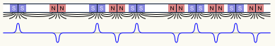
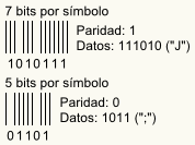
Look at the diagram on the left, which shows several polarity reversals of several lengths. The shorter polarity reversals are half as long as the longer ones, and the short reversals always appear in pairs. A zero is recorded as a long polarity reversal, while an one is recorded as two short ones. When they are read, the zero is received as two pulses separated by a certain interval with nothing but silence in between, while the one is received as two pulses separated by the same interval, but with another pulse right in the middle. The bits in the figure on the left, read from left to right, are therefore 001011.
The most important thing when reading a magnetic stripe is knowing how long the interval between two pulses is. Meaning: these two pulses, do they represent an one or two very fast zeros? As card readers work by swiping the card by hand, the speed at which pulses arrive varies from one card swipe to the next one, and even varies during the swipe itself. Therefore, how does the reader know how long the interval between a zero’s pulses is? This question is answered through the usage of synchronization pulses.
Before the actual data there’s a series of 40 or 50 bits, all set to 0, called “synchronization bits”. When the card begins to be swiped through the reader, the read head produces the pulses corresponding to those zeros, and the reader measures the time elapsed between those pulses. After a few pulses the reader has a good estimate of how long the interval between the pulses of a zero is and becomes ready to receive data. From this moment on, every time the reader receives a pulse it will calculate how long it has been since the previous pulse. If it’s been the approximate duration of the zero-interval, the reader records a zero. If it’s approximately half of that zero-interval, the reader records an one and waits for the second pulse to arrive. The reader also checks whether the pulses arrive slightly fast or slow and adjusts the zero-interval in consequence. This is how the card reader can compensate for changes in the speed at which the card is being swiped.
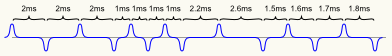
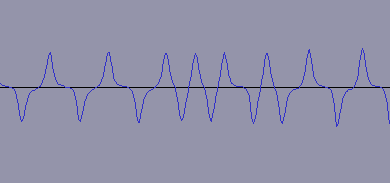
For example, imagine that someone is swiping the card at such a speed that the synchronization pulses arrive at the rate of one every 2 milliseconds and halfway through the swipe they start to reduce the speed: we could receive pulses like the ones in the figure on the right. The first pulses arrive at the rate of one every 2 milliseconds, so it’s clear that each one represents a binary zero. Then come two pairs of pulses separated by 1 millisecond, so each pair represents a binary one. Then the next pulse arrives 2.2 milliseconds later, which means that it’s a binary zero and the card is being swiped more slowly, so we start expecting pulses at the rate of one every 2.2 milliseconds. The next pulse arrives 2.6 milliseconds later, so we record another zero and expect the next pulse 2.6 milliseconds later. Then another pulse arrives 1.5 milliseconds later, which is quite less than the time we expected to receive a pulse, so we record that we’ve received an one and wait for the next pulse which arrives 1.6 milliseconds later. 1.5+1.6=3.1 milliseconds, which is the time we’ll expect to receive the next pulse. The following pulses arrive 1.7 and 1.8 ms later so we have an one. And so on…
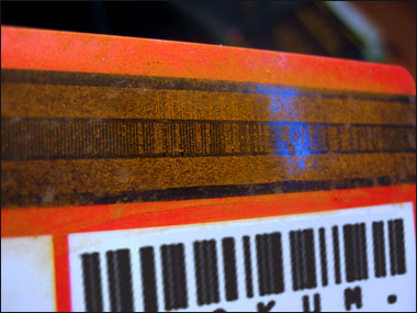
On the left you can see a photo (originally published by The Reverend Anaglyph on “Tetherd Cow Ahead” and reposted with permission) that shows what happens after sprinkling some iron rust powder on a card’s magnetic stripe. Iron rust is attracted by magnets, so it sticks to the areas where the magnetic field is the most intense, and the data recorded in the magnetic stripe become visible to the human eye. Isn’t that cool? You can even tell the zeros and the ones. On the photo you can also see that there are three “tracks” that contain data. The middle track (track 2) was the first one to be standardized, and it contains 75 bits per inch. The top and bottom tracks (1 and 3) are more recent and contain 210 bits per inch.
Each track contains, in this order: a series of synchronization bits, a “sentinel” (which is a series of bits that mark the beginning of data), the actual data, another sentinel (marking the end of data) and, finally, another series of synchronization bits. There are synchronization bits at the beginning and end of the track so that a card can be swiped in either direction. Obviously, if it’s swiped in the reverse direction, the bits will arrive in reverse order, but as the start and end sentinels are different, the card reader can detect in which direction the card was swiped and reverse the bits if necessary.
The data in track 1 are encoded with a 7 bit per symbol schema. These 7 bits comprise a parity bit and 6 data bits. The parity is odd, which means that the parity bit is set so that there’s always an odd number of “1” bits in each 7-bit symbol. The first bit in the symbol is the parity bit, followed by the least significant data bit, and so on until the most significant bit comes last. 6 bits let us represent 64 different values, which gives us room for numbers, upper case and lower case letters, and many punctuation symbols. This 6-bit symbol can be converted into an ASCII character just by interpreting it as a number and adding 32.
Tracks 2 and 3 are encoded with a 5 bit per symbol schema: 1 bit of odd parity and 4 data bits, with the least significant bit first. The 4 bits allow for 16 different values, which gives us room for the 10 digits from 0 to 9 plus 6 control characters. This symbol can be converted into an ASCII character by interpreting it as a number and adding 48.
And now for the last question: what’s stored in each track? Originally, magnetic stripe cards only had one track, which we now call track 2. This track can only contain numeric data, so it stored the card number, expiration date, and a couple more things. Tracks 1 and 3 were added years later. Track 1 can store numbers and letters, so it contains the cardholder’s name and a copy of all data in track 2. Track 3 is almost never used, so it is usually set to all zeros or, occasionally, removed altogether.
Knowing all this I set out to build my own magnetic stripe card reader. As I don’t think I’d be able to build my own read heads, I bought the cheapest card reader I found and opened it up to solder some wires to its read heads. (By happy coincidence the reader did not work properly when it arrived, so I didn’t feel at all bad when I opened it.) As cards have three tracks, the card reader also has three read heads, one for each track. After soldering the wires, I thought about how to connect them to my computer’s microphone socket.
A stereo microphone jack has three leads: a power supply lead and two leads that receive the stereo audio signals. The general idea was to connect the heads for tracks 1 and 2 so that each one of them would send its pulses through a different lead. As there are only two signal leads, track 3 remains unconnected but, as I said before, there rarely is anything interesting in that track, so it doesn’t matter.
The simplest way to connect those read heads would be to connect one of the wires to the power lead and the other one to one of the signal leads, but it turns out that between the power lead and a signal lead there’s a 4-volt potential difference, which I feared would turn the read head into an electromagnet and erase the magnetic stripe as I swiped it to read it. To avoid it I first tried connecting a capacitor in series, but it distorted the signal. In the end I improvised a circuit with operational amplifiers.
(Later on I realized that the 4 V were the open-circuit potential difference; with the read head connected, the potential difference dropped to 100 mV. The experiments I performed suggest that it’s not enough to erase the card, but an ounce of prevention…)
After connecting the read heads I started an audio editor program, I started recording, swiped the card, and got what you can see in the screenshot on the left: a series of pulses received through the microphone socket. After amplifying the signal in software, the pulses are so clear that you can even decode them by eye (0000011010000).
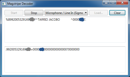
With the card reader connected to the computer and working properly, the one thing left to do was writing a program to decode the pulses. The program I wrote receives signals from the microphone socket, detects the pulses, counts the time elapsed between pulses, extracts the bits, decodes the symbols, converts them to ASCII, and shows the result in a window. The screenshot on the right shows my program after swiping a card from an airline loyalty scheme (the data shouldn’t be sensitive, but I covered some of the numbers just in case). The top box shows the contents of track 1: the card number, my name, and some data that, I guess, serves to validate the card. The bottom box shows track 2: the card number and the same numbers that appear after my name in track 1. Track 3 doesn’t appear because, as I said, it wasn’t connected, but it just contains zeros.
And with this my experiments in reading and decoding magnetic cards have come to an end, at least for now. In the future I might try implementing it in a microcontroller or making a decoder for “exotic” magnetic stripes (public transportation cards, hotel keycards, etc.), but for the moment I’m content with decoding regular cards in a computer.
The card readers currently in the market perform all those processes by themselves and then simulate a keyboard: when the card is swiped, the card reader “types” its stored data very fast. Therefore, it’s not necessary to do anything special to make a program be able to read cards: it only needs to be able to read from the keyboard. If my intention were just to make a card-reading program, everything I wrote about above would be unnecessary: it would have been enough to plug the card reader in and open Notepad. But hey, how boring would the world be if we never did anything unnecessary every once in a while, right?